ZHANGJIAGANG, JIANGSU, CHINA, November 19, 2026 /EINPresswire.com/ — A 5 axis tube bending machine becomes useful when a tube needs coordinated positioning and tooling changes to complete a spatial shape. Aerospace and automotive components can combine several bend planes within a restricted assembly envelope. The machine selection therefore needs to examine the complete route through the equipment. Five controlled axes matter through the movements they provide and the part features those movements make possible.
Let the component define the motion requirement
A tube drawing describes the finished geometry, but production also needs a feasible sequence. Feeding establishes the straight distance to the next bend. Rotation sets its plane, and bending produces the angle around the selected tooling. Additional movements can reposition the head or select another die level. Axis names and their allocation vary between machines. A five axis designation should therefore be read together with the motion description. A machine with the required axis count can still have an unsuitable arrangement for a particular workpiece. The useful comparison is the motion needed at each step of the proposed component program.
For a compact automotive tube, a later bend may need clearance around an earlier one. An aerospace routing can similarly contain closely spaced changes of plane. Review those features before assuming that a larger diameter rating or greater motor power resolves the manufacturing constraint.
Use die levels to address different radii
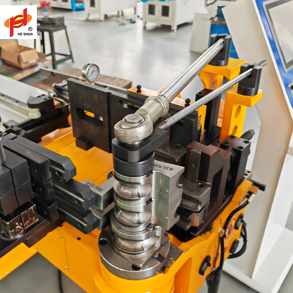
Several bend radii in one tube can require different bend dies. A machine with multiple die levels can select the appropriate tooling during the sequence. The value comes from making that transition while maintaining the required workpiece relationship to the machine.
Heshun offers the 38CNC five axis configuration with three die levels. This configuration is designed for spatial tubes such as automotive exhaust components and seat frames. Each component needs a tooling setup matched to its geometry.
Tooling layout still needs careful review. The installed stack affects clearance and the position from which each bend begins. A multi-level arrangement needs space for the workpiece to move between levels. It also needs the appropriate tooling for each radius and tube section in the selected component.
Distinguish spatial capability from material control
Servo motion coordinates machine positions. The material responds to contact pressure and the support provided during bending. Retaining the section on a demanding tube can require a mandrel and suitable surrounding tooling, regardless of how many axes the controller coordinates.
Springback adds another distinction. The final component relaxes after unloading, so the commanded angle may need compensation. The successful value depends on the actual forming setup and stock. A simulation of the route can establish geometric plausibility without predicting every dimensional effect in the material. A 5 axis tube bending machine should be evaluated with representative production tubing. Measure the released part rather than relying entirely on axis positions. Record the compensation and tooling conditions associated with acceptance so the result can be recovered during later production.
Evaluate interference before committing to the route
The longest leg or an early bend can limit a later movement. During rotation, that leg sweeps through an envelope that may intersect the head or surrounding cell. Review the developing workpiece through the full sequence, including loading and discharge.
A spatial program review can reveal whether a different starting end or bend order is practical. It can also identify a need for a different machine arrangement. Those decisions are more useful before tools and handling equipment are finalized.
The cell itself forms part of the clearance problem. Guarding and collection areas need to accommodate the moving tube, while service access needs room around the machine. A drawing of the base footprint cannot describe these operating spaces. Use the representative component envelope when reviewing the proposed layout.
Qualify the part for its actual application
Aerospace and automotive projects can impose demanding component requirements, but the application label does not supply the acceptance limits. Use the controlled drawing and the applicable project specification. Establish the dimensions and material characteristics that need examination after bending. The trial should include the geometry that is hardest to manufacture. A simple bend may establish a basic machine function while leaving the challenging sequence untested. Choose parts that exercise the relevant die transitions and changes of plane, then judge the result against their own acceptance requirements.
Machine capability also differs from approval for a finished assembly. Bending is one operation within a wider manufacturing route. Any required material traceability or later inspection belongs to that route and the governing product requirements. Avoid inferring finished product qualification from an axis specification.
Compare production flexibility with setup effort
A flexible machine can serve several component families, but each family still creates work in tooling preparation and program management. Assess how frequently production will change and what needs adjustment between parts. The time to recover acceptable output is part of the capacity discussion.
For a stable high volume component, loading and unloading can matter as much as flexibility. Review how the operator or handling system presents the blank and removes the finished shape. A complex tube may require a different handling approach from a straight starting blank.
Choosing a 5 axis tube bending machine is therefore a decision about the whole production method. Relate its motions to the drawing, and relate its changeover approach to the batch pattern. This gives purchasing a clearer basis for comparing equipment configurations and their supplied tooling.
Relate angular control to the assembly envelope
A small direction change can become more visible at the end of a long straight leg. For a simple planar illustration, a leg 500 mm long rotated by 0.2 degrees moves its endpoint sideways by approximately 1.75 mm. This is a geometric calculation for an isolated leg, not a predicted machine error or a complete tolerance analysis.
The example explains why a spatial tube needs acceptance at its interfaces. Several angular and length deviations can interact along a route. The drawing’s datum scheme and the inspection method need to identify the final relationships that matter to the assembly.
A multi-axis configuration gives the process control over particular movements, but those movements need to be evaluated through the finished geometry. Inspecting only an individual bend can leave the overall connection position unresolved.
Use the assembled envelope to choose the representative trial part. A long offset leg may be more informative than a short tube with the same number of bends. This connects the equipment evaluation to the dimensional consequence that engineering needs to manage in production.
Bring the difficult geometry to the application review
Start an equipment discussion with the full spatial drawing and actual stock specification. Mark the minimum straight lengths and explain the assembly datums that govern fit. Include the planned product mix so the proposal can address setup changes as well as cycle operation. To assess a multi-axis bending configuration, share the component through https://Heshun.com/ and identify the sequence or clearance problem that the additional motion needs to solve.
张家港和顺机械制造有限公司
Heshun
Legal Disclaimer:
EIN Presswire provides this news content “as is” without warranty of any kind. We do not accept any responsibility or liability
for the accuracy, content, images, videos, licenses, completeness, legality, or reliability of the information contained in this
article. If you have any complaints or copyright issues related to this article, kindly contact the author above.

Media gallery